Your cart is empty.
Keep shopping

Teach on Udemy
Turn what you know into an opportunity and reach millions around the world.
Learn MoreVerilog Lint essentials for RTL Design Engineer
Rating: 4.2 out of 54.2(82 ratings)
708 students
Verilog Lint essentials for RTL Design Engineer
Step by Step Guide from Scratch
Created byKumar Khandagle
Last updated 11/2024
English
English
What you'll learn
- Role of Lint in DUT analysis
- Reset & Clock best practices
- Naming Conventions & Assignment Operators best practices
- Loop best practices
- Case best practices
- Function & Tasks best practices
Explore related topics
Coding Exercises
This course includes our updated coding exercises so you can practice your skills as you learn.
See a demo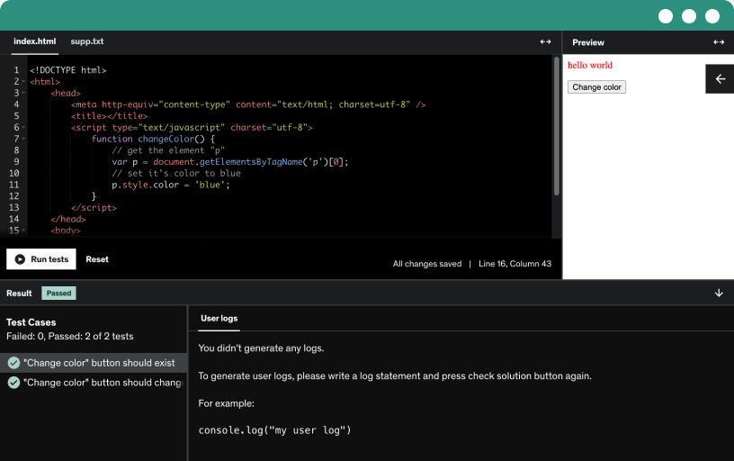
Course content
5 sections • 77 lectures • 3h 10m total length
- Agenda1:33
Explore static and dynamic analysis for DUT, learn where lint fits, and compare lint workflows in Verilator and Vivado 2024, including Vivado ML's early design checks and formats of violations.
- Analysis Types5:50
Examine lint's static and dynamic analysis, learn 81 rules for RTL design, and apply stimuli to a DUT to compare responses with golden data.
- Lint Usage2:31
Use lint as static analysis to catch syntax errors, style violations, non-synthesizable constructs, and unused signals in Verilog, VHDL, and SystemVerilog, with Vivado 2024 lint and Verilator for RTL quality.
- Typical format of Lint violation P13:08
Learn the typical lint violation format used in Verilog lint, including vendor codes, severity like w for warnings and e for errors, and details such as filename and line number.
- Typical format of Lint violation P23:14
Explore lint violation formats across tools like SpyGlass and Viado, deciphering categories from information to fatal errors, and learn when to address, suppress, or improve RTL design issues.
- Typical format of Lint violation P31:15
Describe typical lint violations across Verilator, Verat, and SpyGlass: warnings, categories, rule numbers, file and line details, plus descriptions like implicit real-to-integer conversions; emphasize Verilator and Viado.
- Performing Lint with Verilator4:15
Learn to perform linting and static analysis on Verilog designs with Verilator, including installation on Linux, configuring lint-only checks, and identifying styling and naming issues in top.sv.
- Performing Lint with Vivado 2024.18:44
install Vivado 2024.1 and set up an rtl project. add design sources and run the built-in linter to flag critical violations like dual clock edges, and note naming conventions.
- A1 : IDE Usage Check
- A2 : IDE Usage Check
- Agenda0:41
Explore lint checks using Verilator and Vivado, focusing on reset and clock rules. Review good and bad reset and clock examples, correct violations, and compute violations in the assignment.
- Lint Rules Overview1:31
Organize 81 lint rules into categories by scenario, including reset, clock, assignment operator, signals, naming conventions, and synthesis.
- Reset rules P12:31
Enforce consistent reset edges and a single input reset across the design, choosing synchronous or asynchronous upfront. Avoid multiple reset signals and constants, to prevent race conditions and undefined initialization.
- Reset rules P26:17
Explore the five reset rules for Verilog lint, including edge polarity, single global reset, avoiding multiple asynchronous resets, internal synchronous resets, and constant reset connections.
- Reset rules P31:26
Enforce reset rules with a single polarity and edge sensitivity, avoid mixing sync and async resets, limit to one asynchronous reset per always block, and pass reset as an input.
- Bad Code2:14
Discover how Verilator lint flags mixed reset usage in Verilog RTL designs, showing asynchronous and synchronous resets together and explaining why a single reset is recommended.
- Good Code1:41
Demonstrates good Verilog lint practices with a single synchronous, active-high reset from an external source, simple comparisons, and reset as an input port, plus a warning on top-level file naming.
- Clock rules P11:29
Learn Verilog clock rules: avoid driving a signal with both rising and falling edges, declare clocks explicitly, use a single clock in an always block, and connect clocks to signals.
- Clock rules P25:18
Follow clock rules for synthesizable RTL design: use a single clock edge; avoid dual-edge or derived clocks; declare clock as an external input; employ CDC techniques for multiple clocks.
- Bad Code1:32
Identify clocking violations in Verilog by examining a bad code example that uses both edges, compare Verilator and Viado lint reports, and learn a correct clocking pattern.
- Good Code0:34
Analyze a Verilog design using a single always block on the positive clock edge and a child module directly using the clock input, following clocking rules to the clock signal.
- A3 : Reset Rule Understanding
- A4 : Reset rule understanding
- A5 : Clock rule Understanding
- A6 : Clock rule Understanding
- Agenda0:16
On day three, we discuss assignment rules, naming convention rules, and loop rules with good and bad examples to help you analyze these rules, reinforced by assignments.
- Assignment rules P11:57
Master data handling in Verilog lint rules by enforcing constant data widths, explicit data types, and correct blocking and non-blocking assignments to avoid truncation and race conditions.
- Assignment rules P25:48
Learn how Verilog assignment rules enforce width consistency to avoid truncation and unintended extension, and how implicit type conversion can trigger linter violations without explicit conversion.
- Assignment rules P31:29
Explicitly specify the target bit when assigning a multi-bit signal to a single-bit input to prevent truncation and data loss. Use explicit conversion and select the lsb to avoid misinterpretation.
- Assignment rules P42:52
Use non-blocking assignments in sequential blocks of Verilog and SystemVerilog to update on clock edges, avoiding blocking assignments that cause race-around timing; in combinational blocks, use blocking assignments.
- Assignment rules P52:08
Avoid reading an output port inside a design; use a temporary variable to compute values, then drive the output from that internal signal, upholding the rule outputs send data externally.
- Assignment rules P62:48
Ensure output widths accommodate carry or borrow, with addition results at least one bit wider and multiplication results twice the input width, and prevent inconsistent values by defining complete behavior.
- Assignment rules P72:14
Learn how delays in blocking and non-blocking assignments are non-synthesizable and confined to testbenches, and use pragmas like synthesis translate_off/translate_on, including synopsys translate_off, to separate simulation from synthesis.
- Bad Code3:22
Explore a bad Verilog example that shows improper data handling, including non explicit type conversions and blocking assignments in sequential blocks flagged by Verilator.
- Good Code1:17
Lint Verilog rtl design code by replacing a non-synthesizable type with a consistent 8-bit int, using non-blocking assignments in an always block, and selecting the msb for m_out.
- Operations0:55
Learn how to manage data and signal operations in Verilog RTL design, avoid reading output ports inside modules, ensure widths for carry and borrow, and prevent delays with non-blocking assignments.
- Bad Code1:51
Examine bad versus good Verilog practices by flagging reading an output port inside a module and delays in synthesizable always blocks, demonstrated by a lint warning.
- Good Code0:43
Eliminate the delay by using a temporary variable updated with d_in and comparing it to d_in, avoiding d_out, while counting clock cycles for the delay to pass lint checks.
- Naming rules P11:07
Apply consistent naming conventions and code organization for signals, modules, and constants in Verilog rtl design, using descriptive module names, uppercase constants, and unique clock and reset identifiers across hierarchies.
- Naming rules P25:42
Master Verilog naming rules for modules, constants, parameters, submodules, and signals (reg or wire), clock and reset conventions, using lowercase with underscores or camel case, with meaningful 3–20 character names.
- Naming rules P31:54
Enforce clock naming with a clk prefix or suffix and clearly indicate reset polarity with an active-low suffix like _n, ensuring valid names such as clock_main and reset_n.
- Naming rules P45:21
Learn to name modules with camel or pascal case, capitalizing each word to distinguish them from signals, use meaningful names like memory controller, and prefix signals to avoid conflicts.
- Code0:58
Learn how Verilog lint enforces naming conventions and code organization, ensuring module names match file names and consistent naming for signals, parameters, and variables across hierarchy to avoid violations.
- Loop Rules P11:02
Apply Verilog loop rules for RTL design by avoiding static conditions in a repeat loop, ensuring for-loop stops, using integer drive indices, and preventing initialization and condition variable reuse.
- Loop Rules P24:45
Ensure loop control expressions are static to let the synthesizer predict hardware, using static repeats like repeat(4) and for loops with i = 0; i < 5.
- Loop Rules P32:01
Enforce loop indices as integer types in Verilog lint, avoid time, real, or record iterators, and ensure initialization, control, and step variables use the same variable for proper synthesis.
- While loop : Good & Bad Code2:03
Learn to distinguish good and bad for and while loops in Verilog, avoid infinite loops like while (1), and use always blocks or else blocks for synthesizable, lint-friendly code.
- For loop : Good & Bad Code1:12
Demonstrates a for loop with an incorrect condition using assignment, causing an infinite loop; a lint check flags the issue, and replacing it with less than 10 stops the loop.
- A7 : Assignment operator understanding
- A8 : Assignment operator understanding
- A9 : While loop understanding
- A10 : FOR loop understanding
- A11 : Section Understanding
- Agenda0:13
Explore lint rules for operators, functions and tasks, case statements, and combinational logic, with clear good and bad examples to illustrate proper rtl design practices.
- Function & Task rules P11:31
Enforce nine rules for functions and tasks in Verilog linting, remove unused tasks, avoid recursion and event control, call from sequential blocks, assign all bits, and ensure functions return values.
- Function & Task rules P25:04
Learn Verilog lint rules for tasks and functions: avoid unused or recursive tasks, non-synthesizable event controls, and modifying global signals; pass globals as arguments and implement in always blocks.
- Function & Task rules P32:10
Avoid calling a task inside a sequential block, as it can create an unintentional state machine; ensure functions return a value and set all bits to avoid undefined results.
- Bad Code1:50
Explore Verilog lint essentials by identifying and fixing bad code, such as recursive and unused tasks, replacing them with synthesizable loops to compute factorials and pass Verilator checks.
- Good Code1:13
Apply synthesizable for loops to implement factorial in Verilog, remove unused tasks, and store results in a temporary variable to eliminate lint violations and produce correct factorial values without recursion.
- Case rules P10:56
Master six Verilog case rules for rtl design: complete case, default clause, constant labels, label width match, avoid real numbers and duplicates, ensuring predictable synthesis and reliable hardware behavior.
- Case rules P24:07
Cover all possible states in the case statement, include a default clause to prevent latches, and use constant labels via parameters or local parameters for static, synthesizable hardware.
- Case rules P32:07
Understand why the case select expression must be dynamic, not constant, and why its width must match the case labels to avoid misbehavior in RTL designs.
- Case rules P42:01
Learn Verilog lint rules for case statements, avoiding real or floating-point case labels, understanding X and Z wildcards, and ensuring unique labels to prevent ambiguous matches.
- Bad Code2:33
Analyze a bad case statement in Verilog that uses a 4-bit select but a 2-bit variable, highlights missing default coverage, and shows how lint checks fix width and case completeness.
- Good Code0:55
Modify Verilog code to use two bit selects for select one and select two, cover all states with results and default cases, and run a lint check to remove warnings.
- Combinational logic rules P10:40
Master combinational logic by ensuring all signals are assigned in every path to fully specify behavior, preventing unintentional latches, unpredictable outputs, and timing or debugging issues.
- Combinational logic rules P21:52
Explore latch inference rules in combinational logic, focusing on missing else in if statements and incomplete case statements, and learn how unassigned outputs can retain previous values.
- Good & Bad Code2:11
Understand how incomplete combinational logic can create latches and non-synthesizable designs, and learn to use Verilator lint to enforce complete coverage with an else block for all select values.
- A12 : Function Understanding
- A13 : Function & Case Understanding
- Agenda0:31
Examine rules for structural modeling style, multiple drivers, code hygiene, and synthesis in Verilog lint for RTL design. Review good and bad examples to finalize the 81 essential lint rules.
- Structural Modeling rules P11:30
Learn structural modeling rules for rtl design, focusing on module and port interfaces, single-bit signals in primitives, and proper port width, named association, and complete connections to ensure reliable synthesis.
- Structural Modeling rules P24:48
Learn that Verilog primitives operate on single-bit signals and must not take multi-bit vectors; use bitwise operations or replicated gates, and ensure port widths match.
- Structural Modeling rules P34:11
Ensure module instance connections match the module definition by providing the exact number of port connections for all inputs, outputs, and inouts, preventing floating signals and misbehavior.
- Structural Modeling rules P45:58
Learn to enforce consistent bit ordering across module interfaces in Verilog with modeling rules P4, analyzing big endian and little endian cases, and using lint checks to avoid endianness mismatches.
- Bad Code0:57
Choose between little and big endian for your design, ensure all input ports share consistent bit ordering, and stick to that rule across the design to avoid lint violations.
- Good Code0:35
Learn how to prevent data corruption by avoiding multiple drivers, ensuring clear, predictable signal behavior and avoiding signal integrity issues in RTL design.
- Multiple Drivers P10:33
Identify and prevent multiple drivers in Verilog RTL design by ensuring nets, regs, and wires have a single source, avoiding race-around conditions and unsynthesizable hardware.
- Multiple Drivers P22:48
Learn to enforce memory initialization, remove unused variables and ports, assign read signals to known values, declare nets, use unique names, and ensure complete bus assignments for reliable RTL design.
- Code Hygiene P11:54
Initialize memory with a reset state and a for loop to set all elements, prevent undefined behavior in simulation; remove unused variables and prefix local variables to avoid shadowing.
- Code Hygiene P23:49
Ensure signals read in a module are assigned within an always block to avoid default or unintended behavior, and keep macros constant by using independent macros for different widths.
- Code Hygiene P32:16
Identify and fix signals and variables read without assignment in a module to prevent default values. Avoid redefining macros by using independent macros for different widths.
- Code Hygiene P45:07
Explicitly declare wires to avoid implicit single-bit nets and width mismatches, preventing truncation and unintended nets. Do not drive input ports, and remove unused parameters or unneeded outputs.
- Code Hygiene P52:51
Identify and prevent Verilog port redeclaration by enforcing consistent bit widths. Use reg, wire, or logic for bit access; avoid bit selects on time or integer variables.
- Bad Code1:43
Explore good and bad Verilog code patterns, focusing on memory initialization and unused variables, and learn to fix lint violations by updating memory and removing unused signals.
- Good Code1:00
Initialize memory with reset in RTL designs, avoid synthesizable initial blocks, use a for loop to set all elements, then read element and remove the unused variable to pass lint.
- Synthesis P11:15
Master synthesis essentials for rtl design by applying ten rules to craft synthesizable verilog, including reset priority, always_comb usage, avoiding initial blocks, time declarations, real numbers, events, and nonstandard operators.
- Synthesis P26:38
Master Verilog synthesis rules for RTL design to map to hardware. Avoid time constructs, initial blocks, multi-bit sensitivity lists, case equality, and division; implement safe reset with constants.
- Bad Code2:06
Explore why synthesis-time constructs, initial blocks, wait statements, events, and delays are non-synthesizable. Learn to lint Verilog code with Verilator to replace bad patterns with clean, synthesizable examples.
- Good Code1:10
Adopt an FSM-based, synthesizable RTL design by replacing event control with a reset-decoding always block and next-state logic. Perform a Verilator lint check and confirm no violations.
- A14 : Section Understanding
- A15 : Section Understanding
Requirements
- Fundamentals of Digital Electronics and Verilog
Description
We have two types of analysis for the DUT (Device Under Test). The first type is static analysis, where we examine the design without applying any stimulus. This involves analyzing the constructs and coding patterns to identify early bugs or applying mathematical models to check the correctness of the DUT. Examples of static analysis include linting and formal verification.
The second type is dynamic analysis, where we apply a set of stimuli to the DUT based on test cases and analyze the response to verify functionality.
Linting is crucial in Verilog design to ensure code quality and prevent errors. It enforces coding standards, detects bugs early, and checks for correct syntax and semantics. Using lint tools helps Verilog engineers maintain consistency across codebases, enhance readability, and preempt issues that might not affect simulation but could lead to unexpected results during synthesis.
A key advantage of linting in RTL (Register Transfer Level) design is its ability to detect incorrect usage of clocks, resets, modeling styles, loops, and control structures, which can lead to unsynthesizable designs. The difficulty with these bugs is that they are often hard to identify during debugging, as they are typically logical errors. Early detection of these issues saves designers significant time and effort.
Who this course is for:
- Anyone interested in becoming an RTL Design Engineer.